Status QUAD: 6 StQ-Y 50
Quagi 6 elements 50 Mhz
3 elements quad + 3 elements yagi
950,00 € (iva incl.)

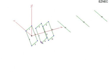
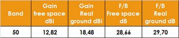
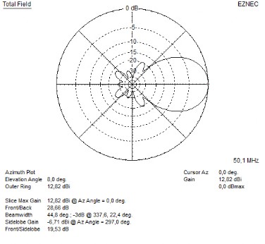
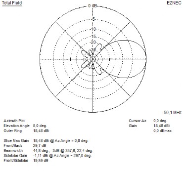
Eznec simulation in free space and real ground
at 10 mt higth
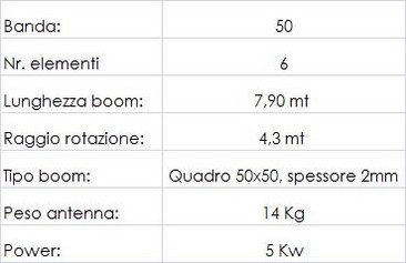
Technical specifications
How this project was born and why choose a Quagi
Status Quad.
This
project was born from the collaboration with one of the best amateur radio
antenna designers, DG7YBN Mr. Hartmut Kluver. The idea behind the project is to
bring together in one single antenna the strengths of two different types of
antennas: quad and yagi. The
quad characteristics are the low noise, the bandwidth, a very high gain while
maintaining a low angle, which is especially useful in DXs. These peculiarities
cannot be exploited to the best by using a single quad element, therefore only
radiator or reflector, but having a completely quad basic electrical structure,
therefore reflector / radiator / director. Among other things, the modeling
analyzes carried out on the quad antennas show a modest increase with the
addition of more than two parasitic elements. It was therefore decided to explore
this hybrid in consideration of the fact that the addition of the yagi
directors allow faster to reach a higher overall gain while maintaining a lean
and light mechanical structure. Below
is the presentation of the electrical project of DG7YBN:
DG7YBN's note about finalizing the 50 MHz 3 plus 2 Extended Quagi:
With Status Quad giving me the opportunity to develop a not seen before design in real I am grateful for the cooperation that Lino offers me. The Extended Quagi combines well known qualities of Quad and Yagi. The driver cell (Reflector, Driven Loop and now in contrast to the Quagi including the most impedance influencing element D1) are resembled by Loops that offer rugged behaviour against environmental influences, small dimension changes and last not least the tendency to offer more bandwidth. This is what the Quad is well know for in shortwave applications. The continuative wave guiding structure is made from lean Yagi-Uda elements. This is the domain of the Yagi as tested in Longyagi applications for demanding performance on VHF/UHF. This way the Extended Quagi offers the stability in frequency response that is welcome for shortwave and lower VHF antenna applications but is as lean as a beam for the further boom.
Mechanical structure and standard equipment
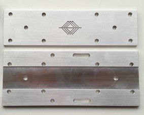
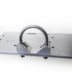
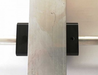
Boom Details
The connecting plate between boom and mast is made entirely of milled and perforated aluminum with CNC machines. The boom housing is dug into the plate to avoid any relative movement or sliding.
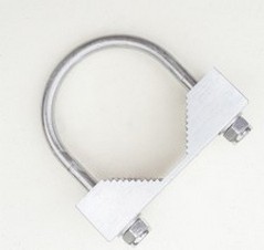
The aluminum U-bolt, are sized to tighten mast with diameter between 40 and 65 mm. The boom is made of 50x50 mm square profile in aluminum 2mm thick.
All bolts including U-bolt are exclusively made of 316 stainless steel.
Antenna elements
The QUAD elements are made with a full fiberglass round diameter 10 mm, the conductor is connected to the elements by nocks made on design and Status Quad project in durable POM UV plastic material.
The QUAD elements are made with a full fiberglass round diameter 10 mm, the conductor is connected to the elements by nocks made on design and Status Quad project in durable POM UV plastic material.
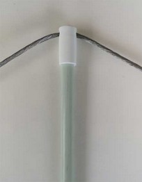
Antenna loops
Antenna loops are made with an aluminum alloy braid 3 mm/6 mmq in diameter; this alloy, like many other details of our quad bikes, has been made and designed for our specific needs. It is not a simple aluminum, but a composite alloy that, with equal conductivity and lightness, ensures greater mechanical strength.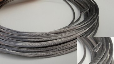
Vertical tie rods
All Status Quad Quagi are equipped with the vertical tie rod kit for the boom. The kit consists of a bracket to be applied on the mast, to which the tie rods in 3mm Mastrant braid are connected. The braid then connected to the boom avoids vertical flexions due to weight and obviously atmospheric stresses.
Yagi elements
The yagi elements are made of aluminum rods with a diameter of 15 mm and a thickness of 2 mm. No brackets or jumpers outside the boom are used to improve and maximize the Quagi electrical efficiency. Passing through the boom allows you to correct the antenna’s electrical design and obtain a better result compared with external fixed elements. To ensure adequate mechanical resistance we have used insulators that perform two very important functions:
1) ensure elements insulation from the boom, opposing the smallest possible surface to the wind
2) cancel the leverage effect of the elements that is exerted through the holes made on the boom. Thanks to the Delrin supports, the lever and mechanical effort are moved from the holes to the surface of the boom.
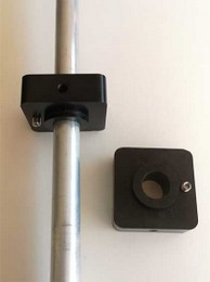
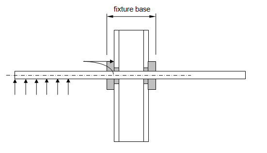
Regarding this very important aspect, an explanatory drawing and the designer's explanation are given below:
"The fix point on the boom is most vulnerable area for breaking with any Yagi element rod. As all the free length left / right side operates as a lever arm in high winds. This insulator guides the element rod through the boom giving very good support at the in that area. As the element is guided by the two plastic bushing concentrically over a long stretch on both sides of the boom. Which gives a broad fastening base which also is able to link forces into the boom shoulder via the wide shoulders of these insulators. With this mounting method through the boom a well known Boom Correction (SM5NSZ's BC.exe) is applied. So that unlike with most other mounting brackets a good performance is guaranteed"
Seguici anche su 

 Sito in

Sito in